Inter-VRF Communication and MPLS PE-CE Connectivity using different routing protocols
6–10 minutes
- Inter-VRF Communication and MPLS PE-CE Connectivity using different routing protocols
- Step 1: First, we will configure IP addresses on all required interfaces and activate IGP (OSPF) in MPLS Core on routers PE1, PE2, R1, R2, R3, and R4.
- Step 2: Enable MPLS LDP and router-id using loopback 0
- Step 3: Configure two VRFs (GREEN and BLUE) on PE1 and PE2 routers and assign RD and RT values.
- Step 4: Enable static/OSPF on the PE1 and PE2 routers inside VRF towards each customer end.
- Step 5: Enable iBGP, MP-BGP, and redistribution in each VRF between two PE routers.
- Step 6: The last final step is to leak one route from each site and verify connectivity
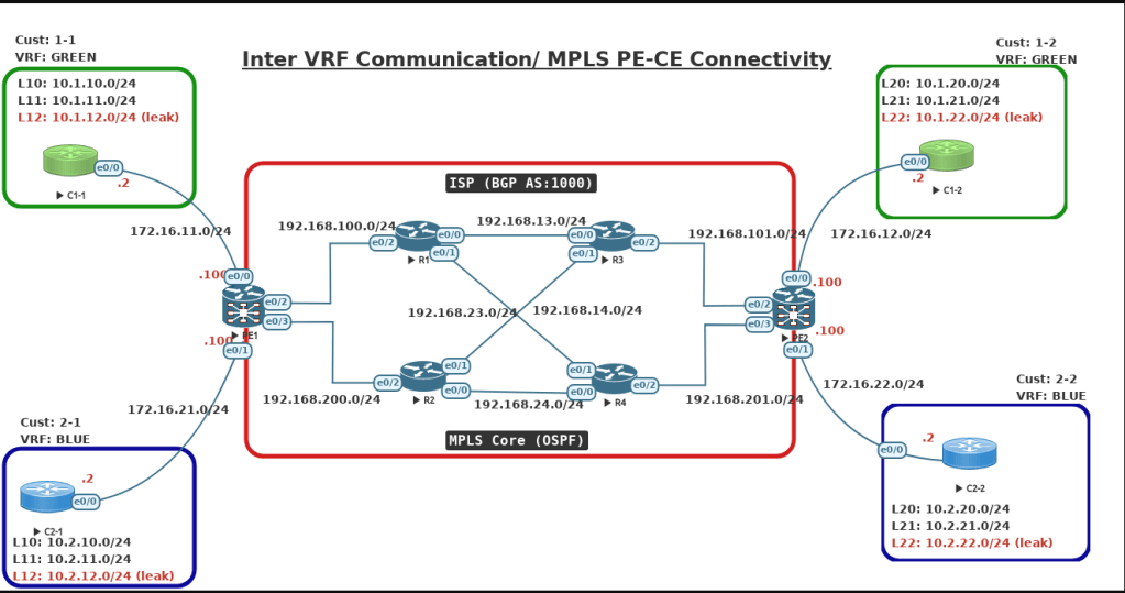
I have used the EVE-NG Emulator tool for all my labs. Below is the full topology I used in this blog. In this blog, I covered the technologies and topics below.
- MPLS Core (using OSPF)
- MP-BGP
- MPLS PE-CE connectivity using different routing protocols
- Inter-VRF Communication
Step 1: First, we will configure IP addresses on all required interfaces and activate IGP (OSPF) in MPLS Core on routers PE1, PE2, R1, R2, R3, and R4.
Note:
- I’m running OSPF as IGP, and you can run any routing protocols. as long as you have full-mesh connectivity across all four routers.
- I like to keep all my transit links between routers as point-point for faster convergence to avoid the DR/BDR election process.
- I also configure the loopback address as /32 (It’s important to note that now I will explain this further in the MPLS section).
R1 Configuration:
hostname R1
interface Loopback0
ip address 1.1.1.1 255.255.255.255
ip ospf network point-to-point
ip ospf 1 area 0
!
interface Ethernet0/0
ip address 192.168.13.1 255.255.255.0
ip ospf network point-to-point
ip ospf 1 area 0
no shut
!
interface Ethernet0/1
ip address 192.168.14.1 255.255.255.0
ip ospf network point-to-point
ip ospf 1 area 0
no shut
!
interface Ethernet0/2
ip address 192.168.100.1 255.255.255.0
ip ospf network point-to-point
ip ospf 1 area 0
mpls ip
no shut
!
router ospf 1
router-id 1.1.1.1
 !
R2 Configuration:
hostname R2
interface Loopback0
 ip address 2.2.2.2 255.255.255.255
 ip ospf network point-to-point
 ip ospf 1 area 0
!
interface Ethernet0/0
ip address 192.168.24.2 255.255.255.0
ip ospf network point-to-point
ip ospf 1 area 0
no shut
!
interface Ethernet0/1
ip address 192.168.23.2 255.255.255.0
ip ospf network point-to-point
ip ospf 1 area 0
no shut
!
interface Ethernet0/2
ip address 192.168.200.2 255.255.255.0
ip ospf network point-to-point
ip ospf 1 area 0
no shut
!
router ospf 1
router-id 2.2.2.2
!
R3 Configuration:
hostname R3

interface Loopback0
 ip address 3.3.3.3 255.255.255.255
 ip ospf network point-to-point
 ip ospf 1 area 0
!
interface Ethernet0/0
ip address 192.168.13.3 255.255.255.0
ip ospf network point-to-point
ip ospf 1 area 0
no shut
!
interface Ethernet0/1
ip address 192.168.23.3 255.255.255.0
ip ospf network point-to-point
ip ospf 1 area 0
no shut
!
interface Ethernet0/2
ip address 192.168.101.3 255.255.255.0
ip ospf network point-to-point
ip ospf 1 area 0
no shut
!
router ospf 1
router-id 3.3.3.3
!
R4 Configuration:
hostname R4
interface Loopback0
 ip address 4.4.4.4 255.255.255.255
 ip ospf network point-to-point
 ip ospf 1 area 0
!
interface Ethernet0/0
ip address 192.168.24.4 255.255.255.0
ip ospf network point-to-point
ip ospf 1 area 0
no shut
!
interface Ethernet0/1
ip address 192.168.14.4 255.255.255.0
ip ospf network point-to-point
ip ospf 1 area 0
no shut
!
interface Ethernet0/2
ip address 192.168.201.4 255.255.255.0
ip ospf network point-to-point
ip ospf 1 area 0
no shut
!
router ospf 1
router-id 4.4.4.4
!
PE1 Configuration:
hostname PE1
!
interface Loopback0
 ip address 11.11.11.11 255.255.255.255
 ip ospf network point-to-point
 ip ospf 1 area 0
!
interface Ethernet0/0
 vrf forwarding GREEN
 ip address 172.16.11.100 255.255.255.0
 ip ospf network point-to-point
no shut
!
interface Ethernet0/1
 vrf forwarding BLUE
 ip address 172.16.21.100 255.255.255.0
 ip ospf network point-to-point
no shut
!
interface Ethernet0/2
 ip address 192.168.100.100 255.255.255.0
 ip ospf network point-to-point
 ip ospf 1 area 0
no shut
 !
interface Ethernet0/3
 ip address 192.168.200.100 255.255.255.0
 ip ospf network point-to-point
 ip ospf 1 area 0
no shut
 !
router ospf 1
 router-id 11.11.11.11
!
PE2 Configuration:
hostname PE2
!
interface Loopback0
 ip address 22.22.22.22 255.255.255.255
 ip ospf network point-to-point
 ip ospf 1 area 0
!
interface Ethernet0/0
 vrf forwarding GREEN
 ip address 172.16.12.100 255.255.255.0
 ip ospf network point-to-point
 no shut
!
interface Ethernet0/1
 vrf forwarding BLUE
 ip address 172.16.22.100 255.255.255.0
 ip ospf network point-to-point
 no shut
!
interface Ethernet0/2
 ip address 192.168.101.100 255.255.255.0
 ip ospf network point-to-point
 ip ospf 1 area 0
no shut
!
interface Ethernet0/3
 ip address 192.168.201.100 255.255.255.0
 ip ospf network point-to-point
 ip ospf 1 area 0
 no shut
!
router ospf 1
 router-id 22.22.22.22
!
Step 2: Enable MPLS LDP and router-id using loopback 0
Note:
- Just make sure “ip cef” is enabled on all routers. It should be enabled by default.
- If your loopback is configured as /32, then you don’t have to worry about configuring point-to-point. This is only true if you are running OSPF as an IGP in MPLS Core. As OSPF treats loopback as a special network type, “Loopback,”
- Don’t worry about the above note if you are not running OSPF
R1, R2, R3, R4 Configurations:
ip cef
mpls ldp router-id loopback 0
!
int eth0/0
mpls ip
!
int eth0/1
mpls ip
!
int eth0/2
mpls ip
!
PE1 & PE2 Configuration:
ip cef
mpls ldp router-id loopback 0
!
int eth0/0
mpls ip
!
int eth0/1
mpls ip
!
int eth0/2
mpls ip
!
int eth0/3
mpls ip
!
Step 3: Configure two VRFs (GREEN and BLUE) on PE1 and PE2 routers and assign RD and RT values.
PE1 Configuration:
vrf definition GREEN
 rd 100:1
 !
 address-family ipv4
  route-target export 100:1
  route-target import 100:1
 exit-address-family
!
vrf definition BLUE
 rd 100:2
 !
 address-family ipv4
   route-target export 100:2
  route-target import 100:2
 exit-address-family
!
interface Ethernet0/0
 vrf forwarding GREEN
 ip address 172.16.11.100 255.255.255.0
no shut
!
interface Ethernet0/1
 vrf forwarding BLUE
 ip address 172.16.21.100 255.255.255.0
 no shut
!
PE2 Configuration:
vrf definition GREEN
 rd 100:1
 !
 address-family ipv4
  route-target export 100:1
  route-target import 100:1
 exit-address-family
!
vrf definition BLUE
 rd 100:2
 !
 address-family ipv4
   route-target export 100:2
  route-target import 100:2
 exit-address-family
!
interface Ethernet0/0
 vrf forwarding GREEN
 ip address 172.16.12.100 255.255.255.0
no shut
!
interface Ethernet0/1
 vrf forwarding BLUE
 ip address 172.16.22.100 255.255.255.0
 no shut
!
Step 4: Enable static/OSPF on the PE1 and PE2 routers inside VRF towards each customer end.
- In my lab, I’m running OSPF on C1-1/C2-1, EIGRP on C1-2, and static C2-2. With this setup and configuration, you will have full exposure.
- If you are running BGP between PE and CE, you don’t have to do redistribution on PE routers. That’s the reason service providers prefer to run BGP.
PE1 and C1-1 Router Configuration:

C1-1 Configuration:
hostname C1-1
interface Loopback10
 ip address 10.1.10.1 255.255.255.0
 ip ospf network point-to-point
 ip ospf 1 area 0
!
interface Loopback11
 ip address 10.1.11.1 255.255.255.0
 ip ospf network point-to-point
 ip ospf 1 area 0
!
interface Loopback12
 ip address 10.1.12.1 255.255.255.0
 ip ospf network point-to-point
 ip ospf 1 area 0
!
interface Ethernet0/0
 ip address 172.16.11.2 255.255.255.0
 ip ospf network point-to-point
 ip ospf 1 area 0
 no shut
!
router ospf 1
 router-id 10.1.1.1
!
PE1 Configuration:
interface Ethernet0/0
 vrf forwarding GREEN
 ip address 172.16.11.100 255.255.255.0
 ip ospf network point-to-point
 no shut
!
router ospf 10 vrf GREEN
 router-id 11.11.11.100
 network 172.16.11.0 0.0.0.255 area 0
!
PE1 and C2-1 Router Configuration:

C2-1 Configuration:
hostname C2-1
interface Loopback10
 ip address 10.2.10.1 255.255.255.0
 ip ospf network point-to-point
 ip ospf 1 area 0
!
interface Loopback11
 ip address 10.2.11.1 255.255.255.0
 ip ospf network point-to-point
 ip ospf 1 area 0
!
interface Loopback12
 ip address 10.2.12.1 255.255.255.0
 ip ospf network point-to-point
 ip ospf 1 area 0
!
interface Ethernet0/0
 ip address 172.16.21.2 255.255.255.0
 ip ospf network point-to-point
 ip ospf 1 area 0
 no shut
!
router ospf 1
 router-id 10.2.2.1
!
PE1 Configuration:
interface Ethernet0/1
 vrf forwarding BLUE
 ip address 172.16.21.100 255.255.255.0
 ip ospf network point-to-point
 no shut
!
router ospf 20 vrf BLUE
 router-id 11.11.11.200
 redistribute bgp 1000 metric 80 subnets
 network 172.16.21.0 0.0.0.255 area 0
!
PE2 and C1-2 Router Configuration:

C1-2 Configuration:
hostname C1-2
!
interface Loopback20
 ip address 10.1.20.1 255.255.255.0
!
interface Loopback21
 ip address 10.1.21.1 255.255.255.0
!
interface Loopback22
 ip address 10.1.22.1 255.255.255.0
!
interface Ethernet0/0
 ip address 172.16.12.2 255.255.255.0
 no shut
!
router eigrp 100
 network 10.1.20.0 0.0.0.255
 network 10.1.21.0 0.0.0.255
 network 10.1.22.0 0.0.0.255
 network 172.16.12.0 0.0.0.255
 eigrp router-id 10.1.1.2
!
PE2 Configuration
interface Ethernet0/0
 vrf forwarding GREEN
 ip address 172.16.12.100 255.255.255.0
 no shut
!
router eigrp VRF-GREEN
 !
 address-family ipv4 unicast vrf GREEN autonomous-system 100
  !
  topology base
   redistribute bgp 1000 metric 1 1 1 1 1
  exit-af-topology
  network 172.16.12.0 0.0.0.255
  eigrp router-id 22.22.22.100
 exit-address-family

PE2 and C2-2 Router Configuration:

C2-2 Configuration:
hostname CE2-2
interface Loopback10
 ip address 10.2.20.1 255.255.255.0
!
interface Loopback11
 ip address 10.2.21.1 255.255.255.0
!
interface Loopback12
 ip address 10.2.22.1 255.255.255.0
!
interface Ethernet0/0
 ip address 172.16.22.2 255.255.255.0
no shut
!
ip route 0.0.0.0 0.0.0.0 172.16.22.100
!
PE2 Configuration:
interface Ethernet0/1
 vrf forwarding BLUE
 ip address 172.16.22.100 255.255.255.0
 no shut
!
ip route vrf BLUE 10.2.20.0 255.255.255.0 172.16.22.2
ip route vrf BLUE 10.2.21.0 255.255.255.0 172.16.22.2
ip route vrf BLUE 10.2.22.0 255.255.255.0 172.16.22.2
!
Step 5: Enable iBGP, MP-BGP, and redistribution in each VRF between two PE routers.
PE1 Configuration
router bgp 1000
 bgp router-id 11.11.11.11
 bgp log-neighbor-changes
 neighbor 22.22.22.22 remote-as 1000
 neighbor 22.22.22.22 update-source Loopback0
 neighbor 22.22.22.22 soft-reconfiguration inbound
 !
 address-family vpnv4
  neighbor 22.22.22.22 activate
  neighbor 22.22.22.22 send-community extended
 exit-address-family
 !
 address-family ipv4 vrf BLUE
  redistribute ospf 20
 exit-address-family
 !
 address-family ipv4 vrf GREEN
  redistribute ospf 10
 exit-address-family
!
PE2 Configuration:
router bgp 1000
 bgp router-id 22.22.22.22
 bgp log-neighbor-changes
 neighbor 11.11.11.11 remote-as 1000
 neighbor 11.11.11.11 update-source Loopback0
 neighbor 11.11.11.11 soft-reconfiguration inbound
 !
 address-family vpnv4
  neighbor 11.11.11.11 activate
  neighbor 11.11.11.11 send-community extended
 exit-address-family
 !
 address-family ipv4 vrf BLUE
  redistribute static
 exit-address-family
 !
 address-family ipv4 vrf GREEN
  redistribute eigrp 100
 exit-address-family
!
With the above steps, we will have end-to-end connectivity between sites in the same VRF as shown below.


Step 6: The last final step is to leak one route from each site and verify connectivity
- From C1-1 will leak 10.1.12.0/24
- From C1-2 will leak 10.1.22.0/24
- From C2-1 will leak 10.2.12.0/24
- From C2-2 will leak 10.2.22.0/24
- It is usually a three-step process.
- Match the route using ACL
- Call that ACL using a route-map and set a unique RT in order to differentiate with outer routes. I’m assigning RT as 100:99 for all routes leaking. You can assign different RT values for each route then you need to configure multiple import statements using that different RT value
- Configure the export map and import routes using the new route-target value.
PE1 Configuration
access-list 1 permit 10.1.12.0 0.0.0.255
access-list 2 permit 10.2.12.0 0.0.0.255
!
route-map LEAK-BLUE permit 10
 match ip address 2
 set extcommunity rt 100:99
route-map LEAK-GREEN permit 10
 match ip address 1
 set extcommunity rt 100:99
!
vrf definition GREEN
 address-family ipv4
  export map LEAK-GREEN
  route-target import 100:99
!
vrf definition BLUE
 address-family ipv4
  export map LEAK-BLUE
  route-target import 100:99
!
PE2 Configuration
access-list 1 permit 10.1.22.0 0.0.0.255
access-list 2 permit 10.2.22.0 0.0.0.255
!
route-map LEAK-BLUE permit 10
 match ip address 2
 set extcommunity rt 100:99
route-map LEAK-GREEN permit 10
 match ip address 1
 set extcommunity rt 100:99
!
vrf definition GREEN
 address-family ipv4
  export map LEAK-GREEN
  route-target import 100:99
!
vrf definition BLUE
 address-family ipv4
  export map LEAK-BLUE
  route-target import 100:99
!


I hope you have a clear understanding of how MPLS PE-CE connectivity works along with Inter-VRF communications.

Leave a comment